


Self-Clinching Fasteners
Broaching Fasteners
Arnold & Shinjo Fasteners
Rivet Bushes
Rivet Nuts
Weld Fasteners
Cage Nuts
Blind Rivets
Inserts for Plastics
Inserts for Stone, Solid
Materials, Composites &
Sandwich Panels
Crown-Nuts
Fast-Con
Installation Equipment
Turned & Cold Formed
special parts made to order
Bespoke fastener design &
development
Fastener & Application
testing
Technical support
ISO 9001
RoHS|WEEE Compliance
REACH Compliance
Conflict minerals
Environmental Policy


SERVICES & SUPPORT


Clinch Nuts
Flush Nuts
Blind Nuts
Miniature Nuts
Nyloc Nuts
Locking Nuts
Floating Nuts
Flush Head Studs
Flush Head Studs for
Stainless Steel
Reduced Flush Head Studs
Thin Panel Non-Flush Studs
High Strength Studs
Thin Panel High Strength
Studs
Flush Head Pins
Flush Head Tapered Pins
Concealed Head Studs
Through & Blind Standoffs
Grounding Standoffs
Thin Panel Standoffs
Quick Release Standoffs
Keylock Standoffs
Concealed Head Standoffs
Flush Panel Screw Assembly
Panel Fasteners
Phillips Head Panel Fasteners
Low-Profile Panel Fasteners
Plunger Assembly
Self-Clinching fastener
Do’s and Don’ts
Self-Clinching fastener
problem solving guides
Self-Clinch in harder panels


NORTHERN PRECISION LIMITED
Specialist Fasteners
+44 (0) 1302 836010
sales@npfasteners.com


Contact us
You can contact us using any
of the methods below.
Unit 3 Durham Lane
Armthorpe
Doncaster
South Yorkshire DN3 3FE
England
+44 (0)1302 836010
sales@npfasteners.com


All rights reserved
© Northern Precision Ltd.
NORTHERN PRECISION LTD
Accreditations
Northern Precision Ltd operate a quality management
system in accordance with ISO 9001.
The ISO 9001 standard is recognised worldwide and
you can be assured of the benefits of working with a
certified company knowing that our management
systems are constantly assessed and approved.

Regulatory
RoHS|WEEE Compliance
REACH Compliance
Conflict Minerals Policy
Environmental Policy
Opening Hours
Mon - Thu
08:00 - 17:00
Fridays
08:00 - 16:30


Registered in England & Wales
Company number 3275391
V.A.T Registration number
GB 684 1384 17


Testing Method
Torque-out testing of Self-Clinching Reduced Head Studs
should be performed by the gradual application of torque as
shown while the test panel is securely held in a vice. The bolt
must be of a sufficient grade to resist thread stripping.
Torque must be gradually applied until failure is observed and
a maximum applied torque reading is recorded. Failure mode
is the stud turning in the panel, cam-out, or dependent on
stud type/size, thread failure.
Performance
Thread
size
M2.5
Installation
(kN)
Torque-out
(Nm)
Pushout
(N)


3.0
Pull-thru
(N)
280
0.5
1900

5.5
455
1.1
2200
M3
4.2
285
0.7
1300
5.5
485
1.3
2450
M3.5
4.3
280
0.7
1450
6.5
495
1.8
2850
M4
5.4
360
1.1
1600
6.6
570
2.2
3350
M5
11.0
525
2.1
1800
1.2mm Aluminium
Test sheet
material
1.2mm Steel
1.2mm Aluminium
1.2mm Steel
1.2mm Aluminium
1.2mm Steel
1.2mm Aluminium
1.2mm Steel
1.2mm Aluminium
1.2mm Steel
19.8
1025
4.5
3800
Max. nut
tightening
Torque (Nm)
0.41
0.41
0.46
0.74
0.58
1.15
0.75
1.70
1.11
2.25


All performance figures are averages obtained over a range of installations and should be used as an indicator
only. Panel material, hole preparation, installation tooling and method can affect part performance. We always
recommend that you carry out your own tests in the actual application. Please call our sales team and we will be
happy to provide you with samples as well as offering technical assistance.
First punch or drill the correct size hole. Do not deburr or chamfer the hole prior to installation as this will
remove material required during the clinching process. It is preferable to install the fastener from the punch
side of the panel.
Place the fastener in the prepared hole in the panel and then locate the fastener in the anvil, ensuring that you
are using the appropriate anvil type for the panel thickness like in the diagram above.
With the panel held level, apply a parallel squeezing force until the head is installed flush to the panel surface.
Do not over squeeze the fastener into the panel as this will result in panel deformation.
When installing Self-Clinching fasteners, please pay attention to the minimum hole centreline to edge and
parent material hardness limitations.
Anvil Dimensions


B
+0.1
3.6
3.1
4.1
4.6
A
+0.08
3.03
2.53
3.53
4.03
Thread size
M3
M2.5
M3.5
M4
5.6
5.03
M5


Countersunk hole style
anvil for 1.50mm or less
panel thickness.
Straight thru hole style anvil
for 1.51mm minimum panel
thickness.

Do not remove any extra material or
chamfer the hole as this could result in
improper installation or reduced
performance.
HRB (ROCKWELL HARDNESS B SCALE)
Ensure that you are installing into a
panel that is ductile and at or below the
published maximum recommended
hardness for the fastener.
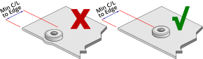
Ensure that attention is paid to the
minimum hole centreline to edge
dimension for each fastener. Installing
too close to an edge or bend could result
in improper installation or reduced
performance. Minimum centreline to
edge dimensions shown for each
fastener apply to one edge only. If this
distance is applied on multiple sides
there will be significant panel distortion
unless the panel edges are supported
during installation.
Material & Finish
Electro Zinc Plated Carbon Steel (ZI) parts are suitable for installation in ductile panels
with a maximum recommended hardness of 80 HRB.
300 Series Stainless Steel (A2) parts are suitable for installation in ductile panels with a
maximum recommended hardness of 70 HRB.
Part Number Examples
Part number is made up as follows:
(Type)-(Thread)-(Length)-(Material/Finish code)
For example:
NFHL-M3-10-ZI (Reduced Head Stud-M3-10mm long-electro zinc plated carbon steel)
NFHL-M4-12-A2 (Reduced Head Stud-M4-12mm long-stainless steel)
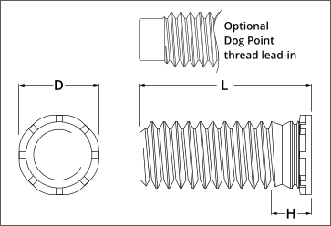
Use part designation NFHLD to specify a dog-point thread lead-in (special order).

Info
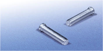
Self-Clinching Reduced Head Studs provide strong low displacement captivated male threads in thin panels and are
suitable for installation closer to the edge of the panel than normal Flush Head Studs.
Utilising a special proven castellated clinch feature, this fastener has good torque-out, pull-through and push-out
characteristics whilst providing a flush finish on the underside of the panel, meaning that minimal surface finishing
is required after installation.
Like all self clinching fasteners they are installed using a parallel squeezing action, so require access to both sides of
the panel.
Reduced Head Studs are available in a range of thread sizes and lengths, manufactured from electro zinc plated
steel, 300 series stainless steel and are suitable for installation in ductile steel and aluminium panels with a
recommended maximum hardness of 80 HRB for steel parts and 70 HRB for 300 series stainless steel parts.
Reduced Head Studs can also be supplied with a dog-point thread lead-in to aid component assembly.
Dimensional Data
Self-Clinching fastener
Do’s & Don’ts
Self-Clinching fastener
problem solving guides
Downloadable
Data Sheet
Back
Installation
Type NFHL
SELF-CLINCHING
REDUCED HEAD STUDS


Push-out testing of Self-Clinching Reduced Head Studs should
be performed by the gradual application of a load as shown
above.
Bushing height should be sufficient to allow free downward
movement of the stud during testing. The bushing bore must
be centred on the head of the stud.
Hardened bush.
A minimum of 6 fully
engaged threads is
recommended on
both sides.


Test panel held
firmly in vice.


Applied torque
from dial measuring
torque wrench.
Minimum grade 5
bolt (grade 8 for
NHTS & NHFE
fasteners).

Pull-through test for Self-Clinching
Reduced Head
Studs should be performed by the gradual application of an axial
load as shown.
A hardened bushing with a through-hole 0.5mm greater than the diameter of the thread should be centred over the
stud and inserted into the test rig lower link. A hardened threaded bushing should be inserted into the test rig upper
link and screwed down onto the stud. An axial load is then gradually applied on a tensile testing machine to separate
the links until a failure point is reached.
Please note that the pull-through values obtained during this test do not indicate the axial strength of the stud threads.
Pull-through values pertain only to the amount of force required to pull the stud through the panel.


Tensile testing rig
upper link
Tensile testing rig
lower link
Hardened bushing
Hardened threaded bushing.
A minimum of 6 fully engaged
threads is recommended.


Applied Load.

Thread dia.
+ 0.5mm


Hardened bushing with
sufficient wall thickness
to withstand applied
compression load.


Head Dia.
+ 1.6mm
Test panel.

Compression rig base.

Torque-through testing of Self-Clinching Reduced Head Studs should be performed by the gradual application of torque as
shown while the test panel is securely held in a vice. The hex nut must be of sufficient grade to resist thread stripping.
Torque must be gradually applied until failure is observed. Failure mode may vary depending on fastener type, size, length
and the properties of the panel the part is installed into. The fastener may actually fracture instead of the head pulling
through the panel.
Please note that the torque-through values obtained during this test do not indicate the axial strength of the stud threads,
the allowable nut tightening torque or the design loading of the assembled component. Torque-through values pertain only
to the amount of torque required to pull the stud through the panel.

Counter-bored bushing detail.


Major Thread
Dia. + 0.08mm
Nominal Major Thread
Dia. + 0.5mm
At Least 2 x minimum
recommended panel
thickness for part.
Axial pull-through (kN) load can be calculated by dividing the torque result (Nm) by (0.2 x major dia. of thread).
Hardened Hexagon Nut
Hardened counter-bored
bushing.
Test panel held
securely in vice.


Applied torque from dial
measuring torque wrench.


A


Length of stud
+3.2mm min.


A


Length of stud
+3.2mm min.


90°


B


