Self-Clinching Fasteners
Broaching Fasteners
Arnold & Shinjo Fasteners
Rivet Bushes
Rivet Nuts
Weld Fasteners
Cage Nuts
Blind Rivets
Inserts for Plastics
Inserts for Stone, Solid
Materials, Composites &
Sandwich Panels
Crown-Nuts
Fast-Con
Installation Equipment
Turned & Cold Formed
special parts made to order
Bespoke fastener design &
development
Fastener & Application
testing
Technical support
ISO 9001
RoHS|WEEE Compliance
REACH Compliance
Conflict minerals
Environmental Policy


SERVICES & SUPPORT


Clinch Nuts
Flush Nuts
Blind Nuts
Miniature Nuts
Nyloc Nuts
Locking Nuts
Floating Nuts
Flush Head Studs
Flush Head Studs for
Stainless Steel
Reduced Flush Head Studs
Thin Panel Non-Flush Studs
High Strength Studs
Thin Panel High Strength
Studs
Flush Head Pins
Flush Head Tapered Pins
Concealed Head Studs
Through & Blind Standoffs
Grounding Standoffs
Thin Panel Standoffs
Quick Release Standoffs
Keylock Standoffs
Concealed Head Standoffs
Flush Panel Screw Assembly
Panel Fasteners
Phillips Head Panel Fasteners
Low-Profile Panel Fasteners
Plunger Assembly
Self-Clinching fastener
Do’s and Don’ts
Self-Clinching fastener
problem solving guides
Self-Clinch in harder panels


NORTHERN PRECISION LIMITED
Specialist Fasteners
+44 (0) 1302 836010
sales@npfasteners.com


Contact us
You can contact us using any
of the methods below.
Unit 3 Durham Lane
Armthorpe
Doncaster
South Yorkshire DN3 3FE
England
+44 (0)1302 836010
sales@npfasteners.com


All rights reserved
© Northern Precision Ltd.
NORTHERN PRECISION LTD
Accreditations
Northern Precision Ltd operate a quality management
system in accordance with ISO 9001.
The ISO 9001 standard is recognised worldwide and
you can be assured of the benefits of working with a
certified company knowing that our management
systems are constantly assessed and approved.

Regulatory
RoHS|WEEE Compliance
REACH Compliance
Conflict Minerals Policy
Environmental Policy
Opening Hours
Mon - Thu
08:00 - 17:00
Fridays
08:00 - 16:30


Registered in England & Wales
Company number 3275391
V.A.T Registration number
GB 684 1384 17


Performance & Testing Method


Push-out
(N)
1350
1800
2250
2700
Installation
(kN)
11
13
14
16
Push-out
(N)
1050
1350
1800
1875
Thread size
M3
M4
M5
M6
Installation
(kN)
13
17
18
22

Steel test panel
Aluminium test panel


All performance figures are averages obtained over a range of installations and should be used as an indicator
only. Panel material, hole preparation, installation tooling and method can affect part performance. We always
recommend that you carry out your own tests in the actual application. Please call our sales team and we will be
happy to provide you with samples as well as offering technical assistance.
Hardened bushing with
sufficient wall thickness
to withstand applied
compression load.


Body Dia.
+ 1.6mm
Test panel.
Compression rig base.

Push-out testing of Self-Clinching Panel Fasteners should be performed by the gradual application of a load as
shown above.
Bushing height should be sufficient to allow free downward movement of the fastener during testing. The
bushing bore must be centred on the body of the fastener.

Applied Load from
compression gauge.

Load should be applied to the shank of the
fastener only. For parts with an L1 dimension
of 0.00 a solid gauge pin can be used. For L1
dimensions greater than 0.00 provision
should be made for the thread protrusion.


A

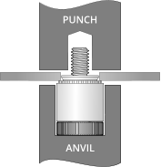
ANVIL

Thread Major
Dia. +2.0mm


PUNCH


Max. screw
extension
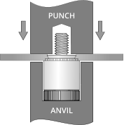
Installation
First punch or drill the correct size hole. Do not deburr or chamfer
the hole prior to installation as this will remove material required
during the clinching process. It is preferable to install the fastener
from the punch side of the panel.
Place the fastener in the recessed anvil with the shank facing up like
in the diagram above. Locate the panel mounting hole over the
shank ensuring the panel is held level.
Apply a parallel squeezing force until the body shoulder is seated
against the panel with no serrations visible. Do not over squeeze the
fastener into the panel as this will result in panel deformation.
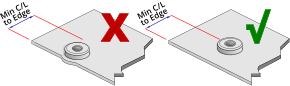
When installing Self-Clinching fasteners, please pay attention to the minimum hole centreline to edge and
parent material hardness limitations.
Anvil Dimensions


B
±0.5
11.05
8.76
11.05
14.35
A
±0.05
10.05
8.45
10.85
12.45
Thread size
M4
M3
M5
M6


Do not remove any extra material or
chamfer the hole as this could result in
improper installation or reduced
performance.
HRB (ROCKWELL HARDNESS B SCALE)
Ensure that you are installing into a
panel that is ductile and at or below the
published maximum recommended
hardness for the fastener.
Ensure that attention is paid to the
minimum hole centreline to edge
dimension for each fastener. Installing
too close to an edge or bend could result
in improper installation or reduced
performance. Minimum centreline to
edge dimensions shown for each
fastener apply to one edge only. If this
distance is applied on multiple sides
there will be significant panel distortion
unless the panel edges are supported
during installation.
Material & Finish
300 Series Stainless Steel (A2) parts are suitable for installation in ductile panels with a
maximum recommended hardness of 70 HRB.
Electro Nickel plated Carbon Steel (CN) parts are suitable for installation in ductile panels
with a maximum recommended hardness of 80 HRB.
Part Number Examples
Part number is made up as follows:
(Type)-(Thread)-(Screw length code)-(Material/Finish Code)
For example:
NPF-M3-40-A2 (Panel Fastener-M3 thread-6.4mm screw length-stainless steel)
NPF-M5-94-CN (Panel Fastener-M5 thread-14.3mm screw length-electro nickel plated
steel)

Info
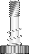
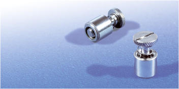
Self-Clinching Panel Fasteners provide a captivated spring loaded screw for use in thin sheet metal where panel to
panel attachment is needed and subsequent access is required. They reduce loose components and so reduce the
risk of loose hardware being lost or falling out and damaging internal components. Actuation can be by tool or
hand.
Utilising a special proven clinch feature, this fastener has excellent pull-out and push-out characteristics whilst
providing a flush finish on the underside of the panel.
Like all self clinching fasteners they are installed using a parallel squeezing action, so require access to both sides of
the panel.
Self-Clinching Panel Fasteners are available in a range of thread sizes and screw lengths, manufactured from 300
series stainless steel, electro nickel plated carbon steel and are suitable for installation in ductile panels with a
recommended maximum hardness of 70 HRB for stainless steel parts and 80 HRB for 300 steel parts.
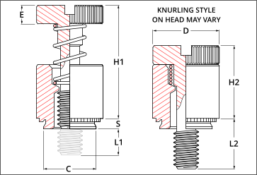
Dimensional Data
Self-Clinching fastener
Do’s & Don’ts
Self-Clinching fastener
problem solving guides
Downloadable
Data Sheet
Back
Type NPF
SELF-CLINCHING
PANEL FASTENERS